Description
REMARKS:
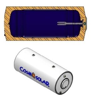
upon request, all below tanks can be dressed with metal grey colour poweder coating
upon request, all tanks can bear either single-phase element (1.5 – 4kw) or three-phase one 1 ½” (6 kW or 9 kW). Safety – regulation thermostat is inclided in both cases.
| TECHNICAL DESCRIPTION | BLGLLA 200 | BLGLLA 300 | BLGLLA 500 / 600 | BLGLLA 800 | BLGLLA 1000 | |||
|---|---|---|---|---|---|---|---|---|
| Cylinder’s diameter | mm | 510 | 510 | 650 | 850 | 850 | ||
| External diameter | mm | 630 | 630 | 850 | 1050 | 1050 | ||
| Height | mm | 1460 | 2000 | 1800/2000 | 1800 | 2000 | ||
| Steel thickness | mm | 2,5 | 2,5 | 3 | 4 | 4 | ||
| max. working temperature | °C | 95 | 95 | 95 | 95 | 95 | ||
| max. working pressure | bar | 10 | 10 | 10 | 10 | 10 | ||
| max. sanitary water admissible pressure | bar | 10 | 10 | 10 | 10 | 10 | ||
| max. operation pressure of coils | bar | 16 | 16 | 16 | 16 | 16 | ||
| P.U. insulation type | hard | hard | soft | soft | soft | |||
| Insulation thickness | mm | 60 | 60 | 100 | 100 | 100 | ||
| max. operation temperature of coils | °C | 130 | 130 | 130 | 130 | 130 | ||
| Solar coil surface Β | sq.mt. | 0,70 | 1,00 | 1,20 | 1,70 | 2,00 | ||
| Heat pump coil surface Α | sq.mt. | 2,20 | 3,90 | 5,20 | 6,10 | 7,40 | ||
| Solar coil capacity Β | Lt | 4,60 | 6,30 | 7,60 | 10,90 | 12,50 | ||
| Heat pump coil capacity Α | Lt | 14,20 | 31,70 | 52,90 | 69,20 | 75,40 | ||
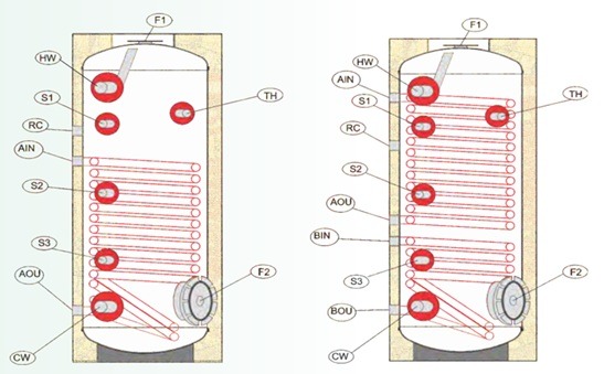
| * upper flange F1 / magnesium rod |
Inch |
140 / DIA22xL500mm | 140 / DIA22xL500mm | 140 / DIA32xL500mm | 196 / DIA32xL500mm | 196 / DIA32xL500mm | ||
| * bottom flange F2 / magnesium rod | Inch | 140 / DIA22xL500mm | 140 / DIA22xL500mm | 193 / DIA32xL500mm | 193 / DIA32xL500mm | 193 / DIA32xL500mm | ||
| Solar coil diameter Β (BIN/BOU) | Inch | 1″ | 1″ | 1″ | 1″ | 1″ | ||
| Heat pump coil diamenter A (AIN/AOU) | Inch | 1 1/2″ | 1 1/2″ | 1 1/2″ | 1 1/2″ | 1 1/2″ | ||
| Cold water inlet CW | Inch | 1″ | 1″ | 1″ | 1 1/2″ | 1 1/2″ | ||
| Hot water outlet ΗW | Inch | 1″ | 1″ | 1″ | 1 1/2″ | 1 1/2″ | ||
| Recirculation inlet R | Inch | 1″ | 1″ | 1″ | 1 1/2″ | 1 1/2″ | ||
| Electrical element’s positioning ΕΗ | Flange F2 | Flange F2 | Flange F2 | Flange F2 | Flange F2 | |||
| Sensor inlets S1, S2, S3 | Inch | 1/2″ | 1/2″ | 1/2″ | 1/2″ | 1/2″ | ||
| Thermometer ΤΗ | Inch | 1/2″ | 1/2″ | 1/2″ | 1/2″ | 1/2″ |